


The Many Passive Layer Causes of VSWR in Cellular
Contents
- Executive Summary
- Introduction
- Understanding VSWR
- The Passive Layer in Cellular Networks
- Common Passive Layer Causes of VSWR
- Diagnostic Techniques
- Preventative and Remedial Measures
- Conclusion
- References
Executive Summary
Voltage Standing Wave Ratio (VSWR) is a critical metric in the performance of cellular networks, reflecting impedance mismatches within the RF path. While active components and environmental interference are often scrutinised, many VSWR issues stem from passive layer components — elements not actively amplifying or processing signals but essential in signal transmission. This paper investigates the diverse causes of VSWR arising from passive infrastructure in cellular networks, their impact on performance, and mitigation strategies for network reliability and efficiency.
1. Introduction
In modern cellular networks — including 4G LTE and 5G — maintaining a low VSWR is essential to ensure optimal signal integrity, energy efficiency, and minimal return loss. VSWR problems lead to reduced coverage, dropped calls, increased noise floor, and damage to sensitive RF equipment. Understanding the root causes of high VSWR in the passive domain allows for more efficient diagnostics, preventive maintenance, and network resilience.
2. Understanding VSWR
VSWR is a measure of how efficiently RF power is transmitted from a power source, through a transmission line, and into a load (e.g., an antenna). An ideal VSWR is 1:1, indicating perfect impedance matching. Any deviation from this implies reflections due to impedance mismatches.
Mathematically:
VSWR=1+∣Γ∣1−∣Γ∣\text{VSWR} = \frac{1 + |\Gamma|}{1 - |\Gamma|}VSWR=1−∣Γ∣1+∣Γ∣
Where Γ\GammaΓ is the reflection coefficient.
3. The Passive Layer in Cellular Networks
The passive layer consists of all non-powered components responsible for carrying RF signals, including:
- Coaxial cables
- Connectors
- Jumpers
- Diplexers/triplexers
- Lightning arrestors
- Antennas
- Combiners
- Tower-mounted accessories
Problems in any of these can contribute to poor VSWR.
4. Common Passive Layer Causes of VSWR
4.1. Poor Connector Termination
Connector-related faults are among the most frequent and impactful causes of passive VSWR issues. Even when high-quality cables and components are used, improper termination techniques create localised impedance mismatches that severely degrade system performance.
Key Fault Modes
Misalignment
- Misaligned connectors — where the inner conductor or dielectric does not seat concentrically — cause step changes in impedance. RF signals are extremely sensitive to even sub-millimetric deviations.
- When the centre pin of a male connector does not properly align with the female socket, this can cause:
- Poor electrical contact
- Arcing or intermittent connection under power
- Permanent damage to the mating surfaces
Improper Torquing
- RF connectors (such as 7/16 DIN, N-type, Nex 10 or 4.3-10) are precision-engineered to specific torque requirements (usually specified in Newton-meters).
- Under-torquing results in:
- Poor shielding continuity
- Microscopic gaps allowing moisture ingress
- Passive intermodulation (PIM) due to micro-arcing
- Over-torquing results in:
- Thread or gasket deformation
- Cracked dielectric or pin collapse
- Long-term unreliability due to mechanical stress
- Actual damage to the connector body
Other Contributing Factors
- Use of non-compatible connector types or materials (e.g., mixing stainless steel and brass) can lead to galvanic corrosion or improper electrical fit.
- Contaminants (dust, grease, oxidation) on connector faces introduce unpredictable resistance and signal reflections.
Best Practices
- Always use a calibrated torque wrench to manufacturer specifications.
- Always use the correct tools for the job.
- Always align mating faces concentrically.
- Inspect connectors with a fibre-optic inspection scope or magnifier for contamination or wear.
- Avoid reusing connectors beyond the manufacturer-stated cycle life.
- Use dielectric grease or sealing gel only when specified, as excess material may cause dielectric displacement or introduce a mismatch.
4.2. Cable Damage or Degradation
Coaxial cables are the arteries of RF systems, and their structural integrity is essential for maintaining constant impedance along the transmission path. Damage or degradation — whether mechanical, environmental, or manufacturing-related — can result in distributed or localised impedance mismatches, significantly elevating VSWR.
Forms of Damage and Their Effects
Crushing and Kinking cause Dielectric Compression or Deformation
- Occurs during installation when cables are pinched, stepped on, or bent beyond their minimum radius. Deforms the internal dielectric or displaces the centre conductor, altering the geometry that defines the cable’s impedance (typically 50 ohms).
- Deforms the internal dielectric or displaces the centre conductor, altering the geometry that defines the cable’s impedance (typically 50 ohms).
- Even a small dent in the outer conductor can induce reflections detectable as broadband VSWR anomalies.
- Affects velocity factor and impedance uniformity.
- It may be imperceptible from the outside but introduces frequency-dependent mismatches, especially at higher bands (>2 GHz).
Outer Shielding Damage
Nicks or breaks in the braid or foil reduce shielding effectiveness and impair the return current path, leading to:
- Increased susceptibility to radiated noise
- Impedance discontinuities causing reflection
UV and Thermal Ageing
Polyethene or PVC jackets degrade under sunlight and heat, becoming brittle and prone to cracking. Exposed inner layers may absorb moisture or suffer from insulation breakdown, contributing to both VSWR and long-term cable failure in braided cables.
Water Ingress Revisited
See Section 4.8, but note: physical damage often facilitates water penetration by breaching the jacket and connector seal.
Detection and Prevention
- Perform Time Domain Reflectometry (TDR) to locate structural faults.
- Use armoured or gel-filled coax for exposed runs.
- Secure cables with proper supports and avoid sharp angles or zip ties that compress the jacket.
- Replace cables showing discolouration, cracking, or excessive stiffness.
4.3. Poor Quality or Mismatched Components
Using components of inconsistent quality, inappropriate frequency rating, or different impedance tolerances is a silent contributor to system-level VSWR degradation.
Low-Quality Components
- Often sourced for cost savings
- Use substandard metals and surface treatments, increasing corrosion and PIM risk
- Have loose manufacturing tolerances that introduce slight but critical impedance variation
- May lack proper shielding or plating, reducing RF isolation
Impedance Mismatch
Components may be labelled "50 ohms" but exhibit actual variations (e.g., 47–55 ohms), especially in connectors or short cables. Even small deviations lead to reflection coefficients significant enough to elevate VSWR at high frequencies.
Frequency Band Limitations
Many components (antennas, filters, surge protectors) are frequency-specific. Using them outside of their rated band introduces:
- Internal reflections due to resonant mismatches
- Poor return loss and ripple in the frequency response
Inadequate Return Loss Specifications
Some manufacturers do not specify return loss (RL) — or do so over a limited band. RL < 15 dB in a component (meaning ~1.43:1 VSWR) is already near the industry threshold; below this is unsuitable for most cellular applications.
Best Practices
- Source components from reputable manufacturers with published RL, PIM, and VSWR data.
- Match all components not just by impedance (50 ohm) but by band-specific optimisation.*
- Avoid mixing connector types or manufacturers without testing return loss at the system level.
- Use vector network analysers (VNAs) to validate new components before large-scale deployment.
4.4 Antenna Impedance Shift
Antennas are designed to present a near-perfect 50-ohm load over their operational frequency range, but real-world conditions often cause their impedance to shift, resulting in reflections that raise system VSWR.
Causes of Antenna Impedance Shift
Proximity to Metallic Structures
Nearby metal surfaces, handrails, tower brackets, or HVAC units alter the antenna’s near field and impedance profile. This is especially problematic with directional panels or sector antennas mounted too close to the tower frame.
Improper Mounting Orientation
Antennas designed for vertical polarisation must be installed accordingly; tilting, twisting, or mounting horizontally causes:
- Polarization mismatch
- Beam distortion
- Increased reflection into the feed line
Environmental Effects
Corrosion of the antenna's connector or radiating elements changes its electrical characteristics. Water ingress into the radome or phased array introduces dielectric loading, shifting the resonant frequency. Ice accumulation changes both shape and dielectric environment — a common seasonal cause of elevated VSWR.
Manufacturing Drift or Damage
Antennas can be detuned due to:
- Internal arcing from lightning surges
- Broken solder joints inside PCB-fed panels
- Ageing materials (e.g., delamination in patch arrays)
Identification
- Elevated VSWR at the antenna port (measured with a portable VNA or site master) that disappears when the antenna is replaced.
- Field strength or coverage maps showing unexpected nulls or dropouts.
- Time-based degradation (e.g., the system worked fine for months but degraded after a storm).
Mitigation
- Maintain proper mechanical spacing (e.g., 1/4 wavelength or more) from metal structures.
- Always weather-seal and inspect antennas regularly.
- Replace antennas showing unexplained VSWR increases or inconsistent radiation patterns.
- Use antennas rated for outdoor use with IP66+ enclosures and UV-stable materials.
4.5 Faulty or Mistuned Filters and Diplexers
Diplexers, duplexers, and filters are sensitive to internal tuning. Even minor drift can degrade matching at certain bands.
VSWR spikes often indicate:
- Thermal cycling damage
- Faulty internal solder joints
- Manufacturing defects
4.6 Improper Grounding and Bonding
A frequently overlooked yet fundamental element of VSWR control is proper RF grounding and bonding. While grounding is often thought of in terms of electrical safety, in RF systems, it plays a direct role in return path integrity and impedance stability.
Why Grounding Affects VSWR
RF signals travel not only through the centre conductor but also as a return current along the shield or outer conductor. Disruptions in this return path, due to poor bonding or floating grounds, introduce reflections just like a mismatched impedance.
Ground loops or discontinuous paths create localised resonances or radiating nodes, especially in high-bandwidth or high-frequency systems.
Typical Grounding Issues
- Inadequate bonding between cable shields and tower or cabinet ground points
- Floating surge protectors or lightning arrestors not tied to a common ground plane
- Use of painted or corroded surfaces as bonding points
- Differences in ground potential between connected components (especially in large distributed antenna systems)
Symptoms
- Variable VSWR depending on environmental conditions (humidity, rain)
- Elevated VSWR on multiple bands simultaneously
- Intermittent system noise or dropped uplink
Mitigation
- Bond all components (cables, surge arrestors, antennas) to a single, low-impedance ground plane
- Use copper grounding straps and serrated washers for improved contact
- Ensure bonding is maintained through tower painting cycles or enclosure replacements
- Verify ground continuity with low-ohm resistance testers
4.7 Jumpers and PIM-Related VSWR
Jumpers — short, flexible coaxial cables used to bridge between rigid cables, components, or antennas — are a known weak point in RF installations and disproportionately contribute to both VSWR and PIM issues.
Why Jumpers Matter
- They are frequently moved, bent, or flexed during installations and maintenance.
- Their short length means even minor faults represent a significant portion of the total signal path.
- They are often the last-installed component and prone to rushed or improper connections.
Key VSWR Contributors in Jumpers
Improper Bend Radius
Exceeding the manufacturer’s minimum bend radius compresses the dielectric and shifts impedance. Sharp bends also risk fracturing the dielectric or delaminating internal layers.
Mechanical Stress
Repeated flexing, hanging weight or ‘springing’ can pull on connectors, leading to partial disconnection or shield separation. Thermal expansion/contraction during seasonal cycles worsens mechanical strain.
Poorly Crimped or Soldered Ends
Poor termination causes:
- Loose centre pin or ground contact
- Air gaps leading to internal arcing
- Increased resistance and localised heating
PIM Sources That Affect VSWR
PIM arises from metal-on-metal contacts in nonlinear junctions (e.g., loose connectors, corroded threads). Although PIM primarily affects signal purity, it is often accompanied by VSWR anomalies, as the same physical faults (looseness, corrosion, arcing) disrupt impedance.
Prevention and Best Practice
- Use factory-assembled, PIM-rated jumpers where possible.
- Minimise bending and never exceed specified flex limits.
- Visually inspect for sheath cracking or discolouration.
- Replace jumpers during antenna upgrades or after a suspected lightning strike.
4.8 Water Ingress and Environmental Contamination
Water ingress is a common but often underestimated source of passive-layer VSWR problems, especially in outdoor cellular deployments where equipment is exposed to variable weather conditions. However, not all moisture exposure leads to elevated VSWR — the critical factor is whether water penetrates the coaxial cable or component deeply enough to reach the dielectric layer.
Potential Water Ingress Locations
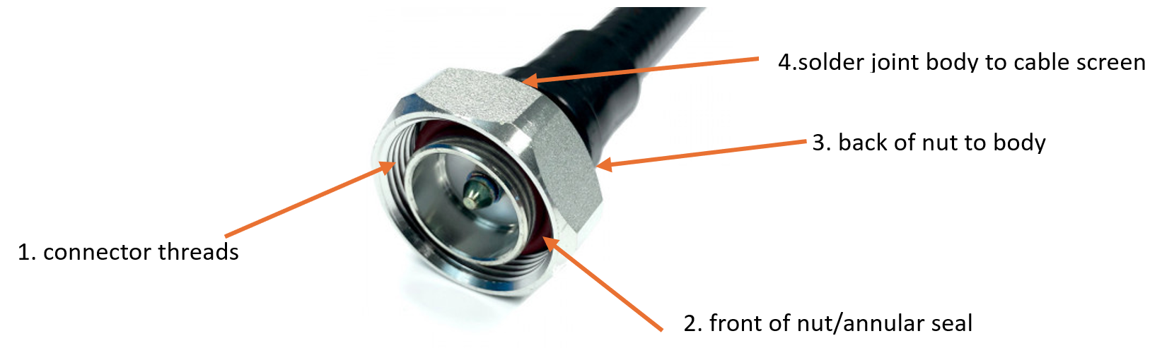
Key to Water/Moisture Ingress Root Causes
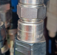
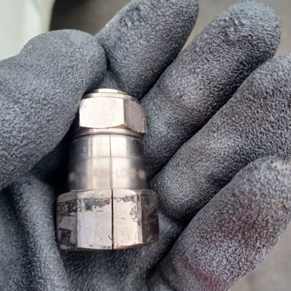
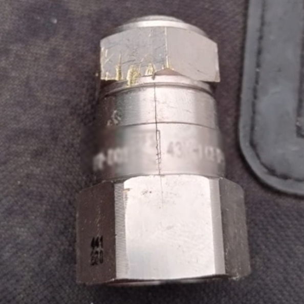
1. Connector Threads
- Thread mismatch/lengths — mating part compatibility
- Incorrect torque
- Angular cable causing excess friction between the mating halves when torquing
- Contaminants/grit in the thread causing excess friction
2. Front of Nut/Annular Seal
- Incorrect torque
- Angular cable causing excess friction or poor seating
- Damaged seal — reuse or incorrect torque
3. Back of Nut to Body
- Angular cable causing excess friction or poor seating
- Contaminants/grit between nut and annular body feature
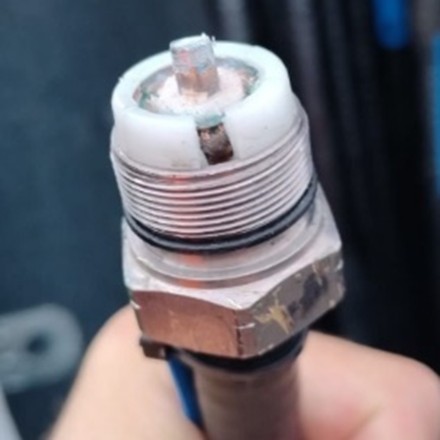
4. Solder Joint – Body to Cable Screen
Many cable manufacturers use manual soldering to effect the electrical joint between the cable screen and the connector body. This relies upon the operator to feed in enough solder at the right temperature (applied by soldering iron) for the correct time to form a non-oxidised (low resistance & non-porous) connection. In this case, an impervious cable boot MUST be applied to this location as it is impossible to fully visually inspect and validate the integrity of the joint for ingress protection.
To provide a highly reliable 360° ingress seal AND controlled low resistance joint, for over a decade of cable manufacture Hughes have used high integrity induction soldering where a preset volume of high silver content solder is wrapped around the joint and high frequency induction consistently heats all of the metal parts to a known temperature that permits full solder flow for a preset time to prevent oxidation and to produce an impervious seal between the cable screen and the connector body. This process creates a highly reproducible low low-resistance joint. The cables are then cooled, visually inspected, and VSWR tested. As this localised heating can mark the cable sheath, a purely cosmetic overmould is then applied that covers any bared copper and provides a location for branding. A second VSWR test is then applied to the finished cable before final visual inspection and QA release.
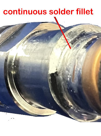
The use of induction soldering is the only accepted way of guaranteeing reproducible electrical and environmental sealing of this type of soldered cable connection.
Mechanism of Impact: Dielectric Saturation
In a coaxial cable, the dielectric (usually a foam or solid polymer such as polyethene or PTFE) serves to maintain the spacing between the inner conductor and the outer shield, ensuring a consistent characteristic impedance — typically 50 ohms in RF systems.
When water penetrates the cable and reaches the dielectric:
- Dielectric constant changes: Water has a high relative permittivity (εr ≈ 80) compared to typical dielectric materials (εr ≈ 1.5–2.2). Even small amounts of moisture in the dielectric dramatically alter the local impedance.
- Local impedance mismatches form: These shifts cause reflection points, which contribute to standing waves.
- Signal attenuation increases: Water introduces additional dielectric loss and conductive paths, especially when mixed with dissolved contaminants or salts.
- Corrosion and long-term degradation: Water also fosters electrolytic corrosion at the interface of the inner conductor and dielectric, potentially worsening VSWR over time.
What Doesn't Matter as Much
Surface wetting or minor condensation on the outside of a connector or cable, if not penetrating to the dielectric, typically has minimal effect on RF performance.
How Water Penetrates the Dielectric
- Compromised connector seals: Damaged or poorly weatherproofed connections allow capillary ingress.
- Improper sealing of end-of-line terminations: Especially in antennas, surge arrestors, or jumpers.
Detection and Diagnosis
- Time-Domain Reflectometry (TDR) can detect impedance anomalies and distinguish between connector faults and dielectric contamination.
- VSWR sweeps across frequency bands: Water-damaged dielectric often shows broadband VSWR degradation rather than sharp peaks.
- Visual inspection and cut-back testing: Physically cutting and examining suspect cable segments often confirms water infiltration.
Prevention
- Use double-sealed or gel-filled weatherproof connectors.
- Ensure all connectors are induction soldered
- Apply weather shielding to all connection points**
- Install drip loops and ensure correct orientation of connectors (e.g., keep connectors upright to avoid pooling).
- Conduct proactive seasonal maintenance, especially after freeze-thaw cycles
4.9 Inadequate Installation Practices
Human error remains a dominant factor:
- Lack of torque wrenches during connector assembly
- Cable routing too close to metallic objects
- Exceeding the (smaller bend) minimum bend radius (MBR) specification of cables
- Grit or other contaminants in the mating threads
- Excessive re-torquing causes seal damage
- Incomplete weatherproofing
5. Diagnostic Techniques
VSWR Sweep (Swept Return Loss Measurement)
Measures the reflection across a frequency band, highlighting mismatch areas.
Distance-to-Fault (DTF) Analysis
Identifies the exact location of reflection points along the transmission path.
PIM Testing
Detects nonlinearities that can correlate with VSWR anomalies.
Visual Inspection & Torque Testing
Often, the quickest way to identify improperly seated connectors.
6. Preventative and Remedial Measures
- Use high-quality, frequency-matched passive components.
- Ensure the cleanliness of all threads and electrical contacts
- Use the correct recommended assembly tools
- Do not grip incorrect parts of the connectors or cables
- Apply manufacturer-specified torque settings.
- Implement stringent installation and maintenance SOPs.
- Seal all outdoor connectors with weatherproofing kits.
- Regularly test and log VSWR during maintenance.
- Replace ageing coax and jumpers proactively.
- Educate field staff on proper connector handling and grounding.
7. Conclusion
Though often overshadowed by active layer complexities, the passive layer remains a major source of VSWR issues in cellular networks. A systematic approach to installation, maintenance, and diagnostics of passive components is essential for ensuring optimal network performance and long-term reliability.
8. References
- 3GPP TS 38.104: Base Station RF requirements
- IEC 61196: Coaxial communication cables
- Anritsu Technical Notes on DTF and VSWR
- CommScope White Papers on Passive Intermodulation
*Hughes Electronics have developed an algorithm to determine the optimum length to frequency pre-assembled cables
** Hughes OneWrap shields all sizes of connectors and cables from water ingress and provides a ‘drip drain’